
What Is Interface Management?
Interface Management is the systems engineering activity that identifies, defines, agrees and controls the interfaces of a system, so that elements developed separately successfully work together when they are integrated.
The discipline covers the interfaces between the system's own elements and those between the system and the outside world: other systems, operators and maintainers, supporting infrastructure and the physical environment.
Interface Management is active through the whole life cycle, from the first description of the system's boundary to operation, maintenance and later modification.
The activity has a technical side and an organisational side:
- Technical: every point where two elements interact is found, what passes between them is described, and both sides are designed, built and verified to the same description.
- Organisational: when the work on a large system is divided among parties, such as a government agency and its contractors, a prime contractor and its suppliers, or teams in different places, each interface is also a boundary between organisations, teams and people.
The Systems Engineering Handbook of the International Council on Systems Engineering (INCOSE) treats interface management as a distinct activity cutting across the agreement, technical management and technical processes, consistent with ISO/IEC/IEEE 15288, the international standard for system life cycle processes. Accordingly, it should be explicitly covered in the systems engineering management plan (SEMP) or a separate interface management plan.
This guide covers what counts as an interface, why interfaces need managing, the work across the life cycle, the records it produces, how it relates to other processes, and how it varies across industries. In addition, a short case study is included describing the loss of Mars Climate Orbiter and the role Interface Management played.
What is an interface?
An interface is the shared boundary between two elements across which they interact.
Force may be transmitted across it, or energy, material or information may pass from one side to the other.
The elements may be hardware, software, people, facilities or whole systems.
An interface is defined by what crosses it and by the characteristics that crossing must have: physical, mechanical, electrical, thermal, data, timing and human.
External and internal interfaces
- External interfaces lie between the system and its environment. They depend on systems the project does not design or control, so they cannot be defined from knowledge of the system alone.
- Internal interfaces lie between the system's own elements. They fall between the areas of responsibility of the engineers who own each element.
In both cases no single element's designer holds all the knowledge needed to define the interface.
That is why defining interfaces, and making sure they are compatible and reliable, is a systems engineering (holistic) responsibility.
Two classifications
Two classifications make identification systematic. The first sorts interfaces by what crosses them, and reduces every interface to four kinds:
- Physical connection: force or torque is transmitted through it, and it is symmetric between the two elements.
- Energy flow: energy passes from one element to the other, in one direction.
- Mass flow: material passes from one element to the other, in one direction.
- Information flow: information passes from one element to the other, in one direction.
A single interface often carries several of these kinds at once.
Unwanted flows count as well as intended ones: waste heat, vibration and electromagnetic interference cross interfaces and also need to be managed.
The second classification sorts the parts that make up an interface by what they do to the interaction:
- Connectors transmit it: a cable, a coupling, a pipe, a switch.
- Isolators inhibit it: a shield, a shock mount, a seal.
- Converters change its form: an antenna, a gear train, a reducing valve, a keyboard.
Interfaces beyond operation
Operation is not the only phase with interfaces. Elements also meet test, ground support and maintenance equipment, transport and handling, and the facilities used to assemble, repair and dispose of them, and these interfaces are often overlooked.
Interfaces with operators, maintainers and users are among the most critical and the hardest to define and test.
In software-intensive systems many interactions are messages and data on shared buses, far less visible than connectors and pipes, and often hiding a significant amount of complexity.
Why interfaces need managing
A large share of system failures occurs at interfaces, and many of the major problems found during integration, verification and validation involve them.
Interface elements can have a critical effect on system performance and reliability. An element can be sound in itself and the system can still fail, because what crosses the interface is not what the other side assumed: e.g. data read as something other than what it is.
The way large projects are organised adds to the risk:
- Interfaces fall between the responsibilities of the people who own each element or system.
- Elements that join non-adjacent parts of a system, such as cables, pipes and linkages, often have unclear ownership and can “fall between the cracks”.
- Contracts for outsourced elements are often placed before the design exists, and each supplier has little insight into the elements built by others.
Interactions, and particularly their underlying causes, can never be fully covered in specification documents.
Keeping each party aware of how its part depends on the others needs both documented agreements and regular direct communication between the people responsible.
Timing matters as well. The longer an interface stays undefined, the vaguer it remains and the more problems it could cause. Late changes to interface requirements are more likely to have a significant effect on cost, schedule and design.
The work across the life cycle
Interface management runs from the system concept through to operation.
Identification
Identification starts with the system concept. The concept of operations is analysed to find the external and internal interfaces, and for each interface the analysis establishes where it originates and ends, what stimulates it, and any special characteristics it has.
The system boundaries, organisational structure and contracting arrangements all show where interfaces will exist, because dividing the work creates an interface wherever two parties' scopes meet.
Identification continues after the concept stage: as the architecture develops, interfaces are added and changed, and detailed design can reveal interfaces the architecture did not show.
Diagrams and matrices make identification more systematic:
- A context diagram shows the system as a single element surrounded by everything external that it interacts with.
- An N² (N-squared) diagram places the system's elements along the diagonal of a square matrix. Each off-diagonal cell records what, if anything, passes from one element to another, and a blank cell states that there is no interaction. Completing the matrix forces every pair of elements to be considered, and shows where conflicts are likely before integration begins.
- The design structure matrix (DSM) works the same way but uses the opposite convention for inputs and outputs.
Functional flow block diagrams (FFBDs), data flow diagrams, failure mode and effects analysis (FMEA) and model-based systems engineering (MBSE) models, such as those in the Systems Modeling Language (SysML), serve the same purpose.
Each identified interaction is assessed for maturity, stability, documentation, threats and risk, with particular attention to external systems the project does not control.
Definition: requirements, then design
Once an interface is identified, it is defined in two separate steps.
Interface requirements come first. They state what each interaction must achieve, as functional, performance, electrical, environmental, human and physical requirements and constraints at the common boundary.
They are one class of system requirements, traced to the parent requirements they come from. At this stage the emphasis is on agreeing the characteristics of the interaction, not on how it will be realised.
Interface design comes second. It sets out how the interaction is realised and what each element looks like at the boundary: the medium, such as a data bus, a wiring harness, a mechanical joint or a radio link, and the details both sides must build to, such as:
- connector pin assignments and voltage levels;
- signal formats and communication protocols;
- mechanical tolerances and timing;
- the format and units of exchanged data.
Both ends of an interface have to be designed to the same definition, and the two designs checked against each other. Where a recognised standard exists, such as a data bus or communication standard, using it avoids defining the interface from scratch and gives access to equipment already built to it.
Agreement and control
An interface definition is an agreement between the parties on either side of it.
Once agreed, the interface is baselined and placed under configuration control.
From then on, no interface requirement or definition changes without a formal review of the change and its impact, and the approval of every party whose design depends on it.
Where an interface requires approval from all sides, the approval must be unanimous. Changes go through the requirements management and configuration management processes, so that each change is documented and communicated to every affected element.
A typical forum is an interface working group, also called an interface control working group (ICWG), made up of technical representatives of the interfacing parties.
It develops interface requirements and definitions, resolves issues with them, keeps communication open between the people responsible for each side, and schedules the interface activities.
It may operate on its own or as part of a wider change control board. It also needs clear roles and responsibilities, rules on how problems are raised and resolved and when each party must provide interface information, and an escalation route for when the two ends cannot agree.
Records and plans
The agreed definitions are recorded. In document-based practice, interfaces are recorded in a family of related documents:
- An interface requirements document (IRD) collects the requirements on an interface.
- An interface control document (ICD), or drawing, records the agreed definition of both sides of an interface between two elements. It is the most common of the set.
- An interface definition document (IDD) describes one side only, typically for a product whose eventual users are not yet known, and is turned into an interface control document once the other side is defined.
- An interface control plan (ICP) sets out how the interfaces will be controlled.
In practice, these terms are often used interchangeably, so be clear about the scope when you interact with them.
These documents are maintained under configuration management and become part of the project's technical data package.
Interface management also records the rationale for interface decisions, the assumptions behind approving or rejecting changes, and the actions taken to correct interface problems.
In data-centric or model-based practice, the same information is held in databases and system models such as SysML, which makes the impact of a change easier to analyse and keeps interface definitions consistent across the architecture.
An interface management plan records the interfaces and their requirements, the preferred interface standards and why, and the tests and certifications that apply to each interface. Projects with many contracts also use an interface register: a single list of the interfaces between scopes of work, used to track each one to completion.
Integration and verification
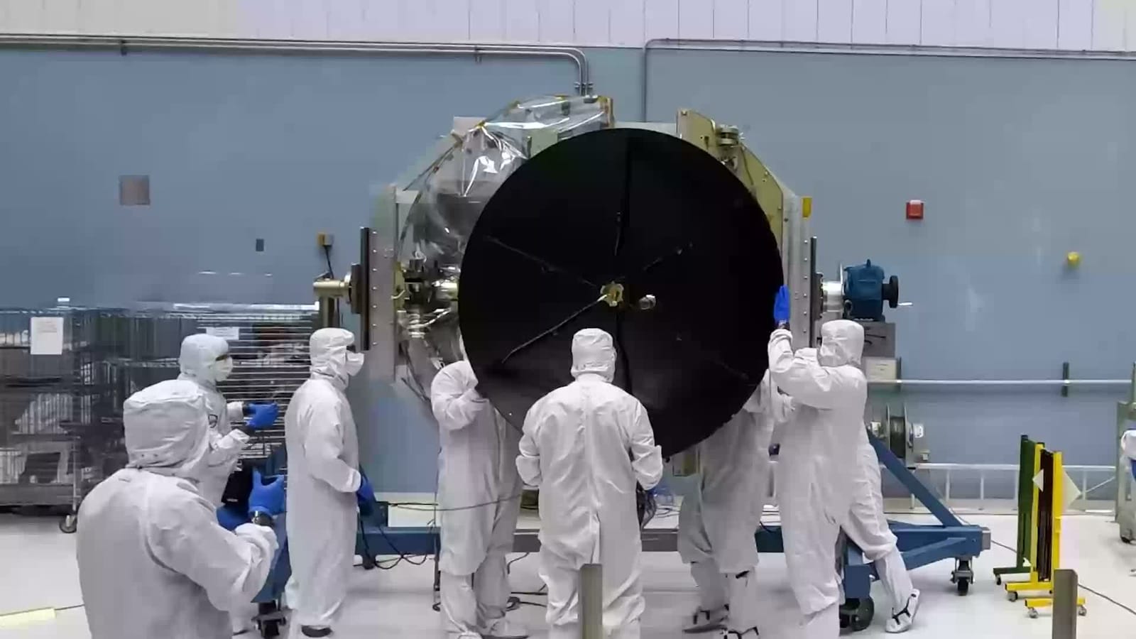
Integration is where interfaces are physically and logically joined, and where any errors not found earlier come to light.
Integration and assembly procedures are reviewed to make sure that interfaces are correctly marked and compatible with their specifications and interface control documents.
Verification and validation cover interfaces at several points:
- Each element is verified against its interface requirements, and interface documents and approved changes set objectives and constraints for the test plans. Verifying interface requirements is a critical part of verifying the system as a whole.
- Interfaces with external systems are validated against what stakeholders need from those interactions in the operating environment.
- The installed state of interfaces is checked when the system is transferred into use.
The order of integration matters. Integrating elements a few at a time, rather than all at once, makes an interface fault easier to locate, which is most valuable for systems being integrated for the first time.
Simulators, models and stubs can stand in for elements not yet available, so that each side of an interface can be exercised before its real counterpart exists.
Operation, maintenance and change
Interface control continues after delivery, and interface processes are controlled through operation as strictly as through design and construction. Some interfaces matter mainly in service: access for maintenance and testing, built-in test, and data exchanged with operators and ground systems.
As products evolve, interfaces have to stay compatible forwards and backwards with elements already in service. In software, managing the versioning and backward compatibility of a published programming interface is the same problem in a different form.
Relationship to other processes
- Requirements management. Interface requirements are requirements, so once baselined they are changed through requirements management.
- Configuration management. Interface documents are configuration items, so configuration management holds their baselines and changes.
- Architecture and design. Interface definitions have to keep pace as the system is decomposed to lower levels.
- Integration and verification. Interface verification is part of system verification, and integration is planned around the order in which interfaces are joined.
- Risk management. The risks at each interface are assessed as part of risk management.
- Supplier agreements. In contracted work, the agreements with suppliers set out how each one will take part in, and comply with, interface management.
On capital projects interface management is treated as a project management practice as well as an engineering one.
Across industries
The activity is the same wherever large systems are built from separately developed parts, but its emphasis varies:
- Aerospace and defence. Government and contractor teams develop subsystems separately and bring them together for integration and test. Interface management centres on interface control documents, working groups and formal change control.
- Capital projects in oil and gas, power and mining are built by many engineering and construction contractors, and interface management centres on the boundaries between their scopes of work. Interfaces are identified during front-end planning, before contracts are awarded, and entered in an interface register. Interface agreements record the information and deliverables one party owes another, often between contractors that have no contract with each other. In process plant design this extends to a common coordinate system, and fixed templates and units for exchanging process data.
- Telecommunications and automotive electronics. Shared network and bus standards let equipment from many suppliers work together.
- Software. Programming interfaces are managed as contracts between modules, and between service providers and their users.
Case study: Mars Climate Orbiter (1999)
Mars Climate Orbiter was launched on 11 December 1998 to orbit Mars as an interplanetary weather satellite. Lockheed Martin Astronautics, the prime contractor, built the spacecraft and ran its operations in flight from Denver. The Jet Propulsion Laboratory (JPL) in Pasadena was responsible for project management, systems engineering and navigation.
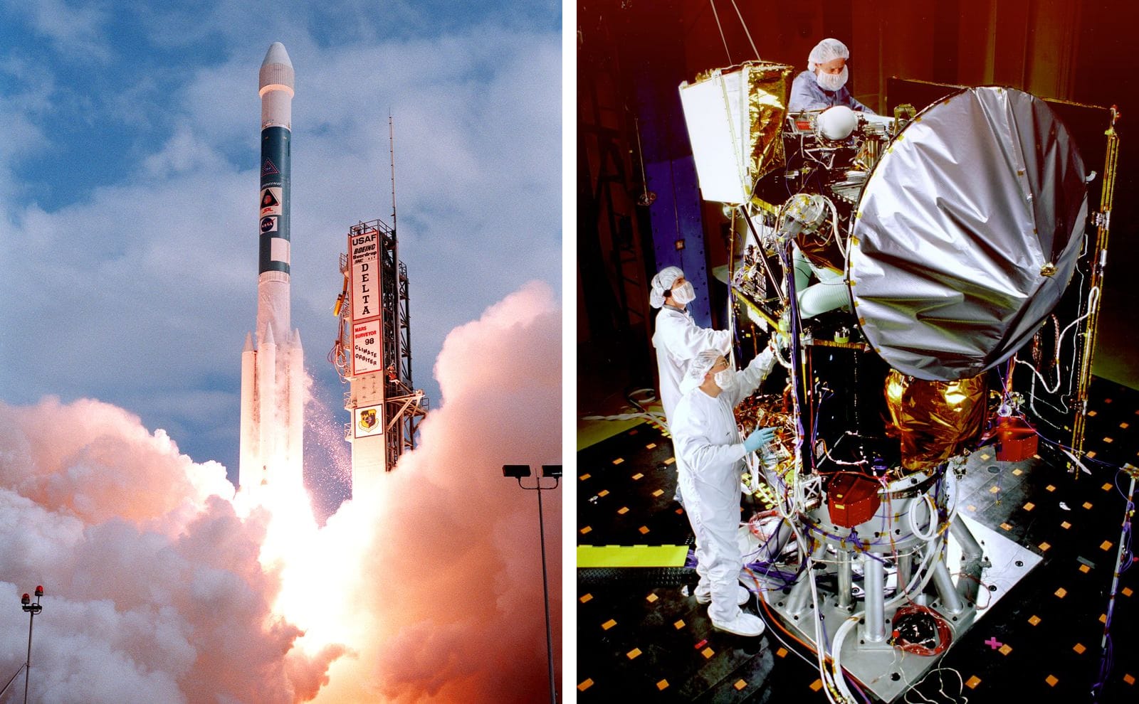
The interface: a file of small forces
The spacecraft pointed itself using reaction wheels: heavy, electrically powered flywheels that turn the spacecraft the opposite way when spun up. External torques, such as the pressure of sunlight, build up momentum in the wheels, so from time to time thrusters were fired to remove it, in a procedure called angular momentum desaturation (AMD). Each firing also gave the spacecraft a small change in velocity, which perturbed its trajectory.
Data from each desaturation was processed on the ground by software called SM_FORCES ("small forces") and written to the AMD file, which JPL's navigation team used to model the small forces when determining the trajectory. The project's Software Interface Specification (SIS) required the thruster impulse in newton-seconds. The ground software reported it in pound-force seconds. One pound-force is about 4.45 newtons, so the navigation software underestimated the effect of every firing by a factor of 4.45. The same calculation on board the spacecraft used metric units and was correct.
Why the error went unnoticed
- Desaturations happened 10 to 14 times more often than the navigation team expected, because the solar array was asymmetric. A daily attitude flip intended to cancel the build-up had been dropped, and the navigation team was not told.
- For the first four months, format errors made the files unusable, and the team relied on emails from the contractor reporting when desaturations occurred.
- Correctly formatted files arrived in April 1999 and within a week indicated that the thruster effects were being underestimated. The conflicts were worked by email rather than through the project's formal anomaly reporting process, and the cause was not found before the spacecraft reached Mars.
Arrival at Mars
Orbit insertion, a burn of about 16 minutes with the main engine, was to capture the spacecraft into orbit around Mars. The final trajectory correction, on 15 September 1999, aimed the closest approach at 226 km; an hour before orbit insertion, orbit determination put it as low as 110 km. The spacecraft could survive no lower than 80 km. On 23 September 1999 the signal was lost behind the planet 49 seconds earlier than predicted and never reacquired. With the small forces corrected, the closest approach was reconstructed at about 57 km. The spacecraft was either destroyed in the atmosphere or passed back into orbit around the Sun.
What the investigation found
The Mishap Investigation Board found the root cause to be the failure to use metric units in the coding of a ground software file, "Small Forces", used in trajectory models. It also found eight contributing causes:
- Undetected mismodelling of velocity changes. The major component of each desaturation's thrust was at right angles to the line of sight from Earth, the only direction in which tracking measures thrust directly, so the systematic error went undetected.
- A navigation team unfamiliar with the spacecraft. The operations navigation team joined shortly before launch and was not given critical information on how the spacecraft's momentum was controlled.
- Trajectory correction manoeuvre 5 not performed. A contingency correction that could have reached a safer altitude was discussed but never executed.
- A systems engineering process that did not adequately address the transition from development to operations. The systems engineering organisation had a number of opportunities to identify the units problem.
- Inadequate communication between project elements. The navigation team was somewhat isolated, and data conflicts were worked by email rather than through the formal Incident, Surprise, Anomaly reporting procedure.
- Inadequate staffing. Before orbit insertion, navigation was handled by the team lead and a single navigator.
- Inadequate training, including in following the interface specification and in treating the small forces software as mission-critical.
- A verification and validation process that did not adequately address the ground software. The SIS was not properly used in developing and testing the small forces software, and the interface control process was not completed, or was completed with insufficient rigour.
The Associate Administrator for Space Science at the National Aeronautics and Space Administration (NASA) said the problem was not the error itself, but the failure of NASA's systems engineering, and of the checks and balances in its processes, to detect it.
The principle
An interface between two organisations' software had a written definition, but one side did not follow it and nobody verified it across the boundary. When the data crossing it looked wrong in operation, the anomaly was handled informally rather than through interface control. An interface is under control only when both sides are built to the same agreed definition, that definition is verified end to end across the boundary, and problems at the interface are worked through the formal process until closed.
Summary
Interface management identifies every point where elements of a system, or the system and its environment, interact; defines each one as requirements and then as a design both sides build to; records the agreed definition, baselines it and controls every change with the approval of every dependent party; and verifies the interface across the boundary at integration and keeps it under control in service.
Interfaces have an organisational side as well as a technical one, because interfaces fall between the people and organisations who own each element. Mars Climate Orbiter shows that a written interface definition is not enough: both sides have to build to it, and it has to be verified across the boundary.
Shorts on this topic
More case studies
Sources
- NASA, NASA Systems Engineering Handbook, SP-2016-6105 Rev 2, section 6.3, Interface Management.
- INCOSE, Systems Engineering Handbook, 5th edition (Wiley, 2023), section 3.2.4, Interface Management.
- A. Kossiakoff et al., Systems Engineering Principles and Practice (Wiley, 2023), section 2.5, Interfaces and Interactions.
- AcqNotes, Interface Management (Defense Acquisition Encyclopedia, updated 23 July 2021).
- IEEE Technology Navigator, Interface management.
- R. Halligan (Project Performance International), What is the scope of interface management and how is the planning for interface management recorded?, 4 October 2022.
- Ascertra, Interface Management 101.
- Wikipedia, Interface control document.
- O. de Weck, Systems Integration and Interface Management, lecture 8, MIT 16.842 Fundamentals of Systems Engineering, Fall 2015 (MIT OpenCourseWare).
- F. Haider, Interface Management 101, Part 1: Engineering Design Phase (video, 2020).
- Mars Climate Orbiter Mishap Investigation Board, Phase I Report, NASA, 10 November 1999.
- NASA Jet Propulsion Laboratory, Mars Climate Orbiter Team Finds Likely Cause of Loss, news release, 30 September 1999.
- NASA Jet Propulsion Laboratory, Basics of Space Flight, chapters 11 and 16.
- NASA Space Science Data Coordinated Archive, Mars Climate Orbiter (1998-073A).
- Wikipedia, Mars Climate Orbiter.