
What Is a Safety Instrumented System (SIS)?
A safety instrumented system (SIS) is an instrumented protection system on an industrial process. It watches for a dangerous condition and, when that condition arises, acts on the process to bring it to a safe state.
A SIS is used where the process design, the control system, alarms and trained operators together still cannot bring the risk of fire, explosion, toxic release or similar major accidents down to a tolerable level. IEC 61511 applies across the process sector, for example "chemicals, oil and gas, pulp and paper, pharmaceuticals, food and beverage, and non-nuclear power generation" (IEC 61511-1, clause 1); fuel storage sites are covered too, as the Buncefield case below shows.
This guide covers how the process industry's functional safety standard defines a SIS, the three kinds of component it is built from, the safety functions it performs, where it sits among a plant's other protection, how its required integrity is set and kept, and its safety life-cycle. It then follows the Buncefield fire of 2005 to show what those principles mean on a real site.

How IEC 61511 defines a SIS
IEC 61511, the functional safety standard for the process industry sector, defines a safety instrumented system as an "instrumented system used to implement one or more SIFs" (IEC 61511-1, 3.2.67). A SIF, a safety instrumented function, is a "safety function to be implemented by a safety instrumented system" (3.2.66). The two definitions point at each other. The system is the hardware and software; the functions are the specific protective jobs it exists to perform. A plant's SIS is understood by listing its functions, not by describing its cabinets.
Relief valves, procedures and containment walls all reduce risk and are protection layers (3.2.57), but they are not instrumented systems. A SIS is defined by being instrumented, not by being automatic: a SIS "may include human action as part of a SIF" (3.2.67, Note 3), and where compensating measures depend on an operator responding to an alarm, "the alarm shall be considered part of the SIS" (11.3.1).
The same idea appears in other sectors, under standards that apply the principles of the generic functional safety standard IEC 61508 to particular sectors: among them IEC 62061 for machinery, IEC 61513 for nuclear systems and ISO 26262 for road vehicles. "Safety instrumented system" is the process-industry term. Other names for the same thing, or for particular kinds of it, are used in practice: emergency shutdown system (ESD), safety shutdown system, protective instrument system and safety interlock system.
Sensor, logic solver and final element
Every safety instrumented function is built from three kinds of component.
- A sensor "measures or detects the process condition" (3.2.73). Examples are pressure, level, temperature and flow transmitters, and simple process switches that change state at a set point.
- A logic solver "performs one or more logic function(s)" (3.2.36). It takes the sensor signals, compares them with the trip conditions, and decides whether to act. It may be relays, solid-state electronics, or a programmable safety controller that resembles a hardened programmable logic controller (PLC).
- A final element "implements the physical action necessary to achieve or maintain a safe state" (3.2.22). Typically this is a shutdown valve with its actuator and solenoid, a motor that is stopped, or switchgear that is opened.
"Sense, decide, act" is a teaching shorthand for this structure. The standard does not define a SIS as three steps, but its three component definitions map onto it directly.
A SIS also includes everything the three parts need to work: "communication and ancillary equipment (e.g., cables, tubing, power supply, impulse lines, heat tracing)" (3.2.67, Note 1). It may also include software. A shutdown valve with no instrument air, or a transmitter whose impulse line has blocked, is as much a failure of the SIS as a faulty controller.
In a function with a single channel, all three parts must work: a sensor that does not see the condition, a logic solver that does not decide, or a valve that does not move each defeats the function on its own. Redundant architectures exist to tolerate such faults.
One system, many safety instrumented functions
Those three parts are assembled function by function. A single SIS can implement many separate safety instrumented functions: a high-pressure trip on one vessel, a high-level trip on a tank, a low-flow trip on a furnace. Each function is specified, designed, analysed and tested as its own entity.
Many safety instrumented functions take the process to a safe state: stop a feed, close an isolation valve, depressurise a vessel. IEC 61511's model of protection layers also places safety instrumented systems in the mitigation layer, which limits the consequences of a hazardous event, as well as the prevention layer (Figure 9).
A safe state is the "state of the process when safety is achieved" (3.2.63). It is not always "everything off". Some processes pass through intermediate states on the way to a safe one, and for some situations a safe state "exists only so long as the process is continuously controlled" (3.2.63, Note 2). Defining the safe state for each function is part of specifying it.
One protection layer among several
A safety instrumented function is never the only protection against its hazard. IEC 61511 defines a protection layer as "any independent mechanism that reduces risk by control, prevention or mitigation" (3.2.57), and gives as examples process design (such as vessel size), mechanical devices (such as a relief valve), a SIS and administrative procedures (such as an emergency plan).
The standard's illustration of protection layers (Figure 9) builds outward from the process itself:
- the process;
- control and monitoring: the basic process control system, process alarms and operator supervision;
- prevention: mechanical protection systems, process alarms with operator corrective action, and safety instrumented systems;
- mitigation: mechanical mitigation systems, safety instrumented systems and operator supervision;
- plant emergency response, such as evacuation procedures;
- community emergency response, such as emergency broadcasting.
Safety instrumented systems appear in both the prevention and the mitigation layers, matching the two kinds of function described above.
A safety instrumented function is added where the risk that remains after the other layers is still more than an organisation will tolerate. The risk reduction that the SIS and the other protection layers must deliver together, so that the tolerable risk is not exceeded, is the necessary risk reduction (3.2.42); a SIF is allocated the part of it the other layers do not provide (9.2.1). Because the layers are counted together, each one claimed must be independent of the others and of the cause of the hazard; the definition of a protection layer makes independence part of what the term means.
Separate from the basic process control system
Independence matters at the innermost layer too. Every process plant already has a control system that runs it: the basic process control system (BPCS), which makes "the process and its associated equipment … operate in the desired manner but which does not perform any SIF" (3.2.3). It uses the same kinds of component as a SIS: sensors, controllers and valves.
The control system can itself cause the upset the SIS must catch. A failed transmitter or a stuck control valve in the control system can start a process drifting towards danger. If the protection relied on the same transmitter, the same controller or the same valve, the failure that caused the demand would also defeat the response.
IEC 61511 therefore requires that, unless the control system is itself built to the standard, the SIS be "separate and independent from the BPCS to the extent that the safety integrity of the SIS is not compromised" (11.2.4). Information may pass between them, but not in a way that compromises the safety function. The standard also caps the risk reduction a conventional control system can claim as a protection layer at a factor of 10 (9.3.2), and notes that the control system "may also be an initiating source for the demand on the protection layer" (9.3.2, Note).
How much a function must deliver: the safety integrity level
The necessary risk reduction sets how reliable each function has to be. That target is the safety integrity level (SIL), and it belongs to the function, not to the system. A SIF "is designed to achieve a required SIL which is determined in relationship with the other protection layers participating to the reduction of the same risk" (3.2.66, Note 1). One SIS may carry functions with different SIL requirements, and where they share hardware or software, that shared part must meet the highest SIL of the functions it serves (11.2.3). Describing a whole system as "a SIL 2 system" therefore misdescribes it.
Many process SIFs operate in demand mode: they sit dormant through normal operation and act only when the dangerous condition arises. For a low-demand function, the target is usually the average probability that the function will fail to act when demanded, the average probability of failure on demand (PFDavg), banded into four levels (IEC 61511-1, Table 4):
- SIL 4: PFDavg ≥ 10−5 to < 10−4; required risk reduction > 10,000 to ≤ 100,000.
- SIL 3: PFDavg ≥ 10−4 to < 10−3; required risk reduction > 1,000 to ≤ 10,000.
- SIL 2: PFDavg ≥ 10−3 to < 10−2; required risk reduction > 100 to ≤ 1,000.
- SIL 1: PFDavg ≥ 10−2 to < 10−1; required risk reduction > 10 to ≤ 100.
Functions that are called on continuously, or very frequently, are instead specified by an average frequency of dangerous failure per hour (Table 5). How either measure is calculated, and the architectural constraints that come with each level, are covered in What is SIL?
Hidden failures, diagnostics and proof testing
Demand mode brings a particular weakness. A demand-mode function spends almost all of its life doing nothing, waiting for the condition it protects against. Throughout that time, a component can fail in a way that would stop the function working, and nothing in normal operation will reveal it. A shutdown valve can stick; a level detector can stop following the level; a device can be left bypassed after maintenance. The plant runs normally because nothing has asked the function to act.
Two mechanisms exist to find these hidden failures before a real demand does.
Diagnostics are frequent automatic tests to reveal faults (3.2.15). They do not detect every dangerous failure: the fraction they do detect is the diagnostic coverage, which by definition does not include faults detected by proof tests (3.2.15.1).
Proof testing is the "periodic test performed to detect dangerous hidden faults in a SIS so that, if necessary, a repair can restore the system to an 'as new' condition or as close as practical to this condition" (3.2.56). The standard requires that proof tests follow a written procedure, that "the entire SIS shall be tested including the sensor(s), the logic solver and the final element(s)" (16.3.1.2), and that the test interval be set from the reliability calculation for the function as installed (16.3.1.3). The interval is part of the design: the longer a hidden failure can sit undetected, the higher the probability of failure on demand.
A proof test also has to return the function to service working. A test that leaves the function disabled removes the protection while creating a record that it was checked, which gives a false sense of security.
The same logic governs bypasses. Instruments in a SIS sometimes have to be bypassed for maintenance or start-up. The standard permits continued operation with a SIS device in bypass "only … if a hazards analysis has determined that compensating measures are in place and that they provide adequate risk reduction" (16.2.4). When a dangerous fault is found, compensating measures must be taken; if safe operation cannot be maintained, the process must be taken to a safe state (11.3.1).
The safety life-cycle
Proof testing and bypass control show that a SIS has to stay right long after it is designed. IEC 61511 organises the work, from the hazard study that calls for a SIS to the day it is removed, as a safety life-cycle, each phase defined by its inputs, outputs and verification activities (6.2.2). The phases shown in the standard's life-cycle figure are:
- hazard and risk assessment;
- allocation of safety functions to protection layers;
- the safety requirements specification for the SIS;
- design and engineering of the SIS;
- installation, commissioning and validation;
- operation and maintenance;
- modification;
- decommissioning.
Running alongside all of these are management of functional safety, functional safety assessment and auditing, safety life-cycle structure and planning, and verification. The design and development of other means of risk reduction sit beside the life-cycle; the standard gives no detailed requirements for them.
Two features of the life-cycle stand out. First, the safety requirements specification (SRS) must be sufficient to design the SIS. For each function it states, among other things, the safe state, the required SIL and mode of operation, the trip points, the response time needed to reach the safe state, and the proof test interval and how the test is done (10.3.2); proof tests later check the SIS against it (16.3.1.1). Second, the life-cycle continues long after commissioning. Operation, maintenance, modification and decommissioning are phases with requirements of their own.
IEC 61511 was first published in 2003, based on IEC 61508; the second edition was published in 2016, with an amendment in 2017. In the UK it is published as BS EN 61511.
What a SIS does not do
A SIS does not make a process safe on its own. It closes a defined gap in risk that the other layers leave open, and its required integrity is set by the size of that gap. It does not replace good process design, a well-run control system, competent operators or containment.
IEC 61511 applies where safety instrumented functions protect "personnel, … the general public or … the environment" (clause 1 j)); its concern is the hazards of the process, not every workplace hazard.
Case study: Buncefield, 11 December 2005
What happened
The Buncefield oil storage depot at Hemel Hempstead, Hertfordshire, close to Junction 8 of the M1 motorway, was the fifth largest fuel distribution site in the UK. It supplied fuel to London and the south-east, including jet fuel to Heathrow and Gatwick, and the Maylands Industrial Estate lay immediately to its west. It was a top-tier site under the Control of Major Accident Hazards (COMAH) Regulations 1999.
From 18:50 on Saturday 10 December 2005, Tank 912, with a capacity of 6 million litres, was filling with unleaded petrol from a pipeline. The tank had two forms of level protection. An automatic tank gauging system (ATG) measured the level and displayed it in the control room, with three alarms: a "user" level, a "high" level and a "high-high" level. Separately, an independent high-level switch (IHLS), set above the ATG alarms, was intended to stop the filling automatically, by closing valves on the incoming pipelines and sounding an alarm, if the level reached an unintended height.
At 03:05 on Sunday 11 December the ATG display "flatlined": it stopped registering the rising level although the tank kept filling. Because the reading stayed below every alarm set point, none of the three alarms could operate, and the control room, which worked to alarms, was not alerted. The IHLS also failed to register the rising level, so its final alarm did not sound and the automatic shutdown did not happen. By 05:37 the tank was full and petrol began to spill from vents in the roof.
A vapour cloud formed and spread in the windless conditions to a diameter of about 360 metres, reaching beyond the site. At 06:01 the fire alarm was pressed, starting the firewater pump, and a vapour cloud explosion followed almost immediately, probably ignited by a spark caused by the pump starting. By then over 250,000 litres of petrol had escaped. There were no fatalities; over 40 people were injured. The fire, the largest seen in peacetime UK, engulfed over 20 fuel tanks and burned for five days.
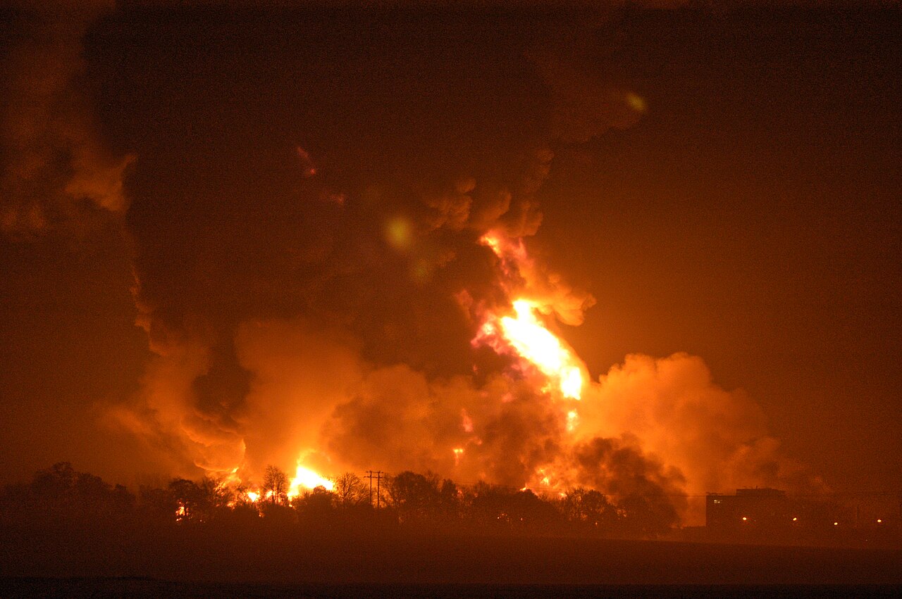
Why the protection did not work
The independent high-level switch had been disabled by its own test. The switch, fitted to Tank 912 on 1 July 2004, had a check lever that let staff activate the switch and its alarm circuit without the tank filling to that level. The lever had three positions. The horizontal one was the normal operating position. Raising the lever tested the switch. Lowering it was the test position for a low-level installation of the same switch; on a high-level installation, lowering the lever disabled the switch. A padlock was meant to hold the lever in the horizontal position. Nobody at the installer or the site understood the padlock's purpose, and the switch was installed without it. After periodic tests the lever was left either in the disabled position or free to fall into it. The switch was tested, and the test left it inoperable.
The gauge had a record of sticking. The ATG servo-gauge on Tank 912 had stuck 14 times between 31 August 2005, when the tank returned to service after maintenance, and the night of the incident. The symptom was cleared, sometimes by the supervisors and sometimes by the maintenance contractor, but the cause was never properly identified, and the sticking was not consistently recorded in the defect log. One supervisor had asked for a back-up IHLS because the gauging system was becoming unreliable.
Each layer's weakness increased the reliance on the other. Because the gauge was unreliable, there was more dependence on the high-level switch; because the switch was frequently left inoperable, there was more reliance on the gauge. Management did not scrutinise their combined unreliability, and the overall control of tank filling was seriously weakened.
The supply chain did not carry the safety requirement. The switch's designer did not pass on the safety-critical role of the padlock; the installer did not find it out; the site operator did not exercise enough oversight of ordering, installation and testing to understand how the switch worked. Replacing the switch in 2004 should have gone through a formal management of change process, including what it meant for testing. None was carried out.
The investigators placed these technical causes inside wider management failings: deficient tank-filling procedures, increased throughput and pressure on staff, poor visibility of incoming flows, inadequate fault logging, and audits that checked whether systems existed rather than whether they worked.
What changed afterwards
Five companies were convicted at St Albans Crown Court, with proceedings completed on 16 July 2010: Total UK, Hertfordshire Oil Storage Ltd, British Pipeline Agency, Motherwell Control Systems 2003 Ltd (which supplied and installed the IHLS and maintained the gauging system) and TAV Engineering (which designed, manufactured and supplied it). Fines totalled £5.35 million and the court ordered costs of £4.08 million.
An independent ultimate high-level switch was not new: the Buncefield Major Incident Investigation Board (MIIB) described ultimate high-level detection as "common practice", and Tank 912 had one. What the Board found missing was a requirement for overfill prevention to be automatic; BS EN 61511 itself "does not require such systems to be automatic in operation". It recommended that sites of this type fit "a high integrity, automatic operating overfill prevention system … that is physically and electrically separate and independent from the tank gauging system", engineered, operated and maintained to "the recognised industry standard for 'SIS', Part 1 of BS EN 61511", with all its elements proof tested often enough to maintain the specified SIL in practice.
The Process Safety Leadership Group's standards for fuel storage sites then set fully automatic overfill protection to SIL 1, as defined in BS EN 61511, as the benchmark for UK sites storing gasoline in bulk. SIL 1 is the minimum, not a fixed target: each dutyholder determines the appropriate SIL by risk assessment, with layer of protection analysis (LOPA) named as a suitable method. No source read gives a SIL for the Tank 912 switch or says it was assessed to BS EN 61511.
The IHLS was intended to do what a safety instrumented function does: detect a dangerous level, decide, and automatically isolate the inflow. Buncefield shows what each principle in this guide looks like when it is missed:
- A demand-mode function fails silently. The switch was disabled while the plant ran normally, and nothing revealed it except the real demand.
- A proof test must leave the function working. The switch's test left it inoperable, with a record that it had been tested. Test procedures, and the design of test facilities, are part of the safety function.
- Protection must be independent of the monitoring it backs up. Where each was relied on to cover the other's weakness, the overall control of tank filling was seriously weakened.
- A known fault in a protection layer calls for compensating measures. The gauge had stuck 14 times without the cause being found or the fault being properly logged, and no compensating measure was put in place.
- The life-cycle includes everyone who touches the function. A safety requirement not passed down the supply chain, and a replacement that bypassed management of change, undid the design.
A safety instrumented system only delivers a risk reduction if it is adequately maintained.
Summary
A safety instrumented system is the instrumented protection on a process: sensors, logic solvers and final elements that together perform safety instrumented functions, each taking the process to a safe state or limiting the consequences of a hazardous event. Each function closes a defined gap in risk left by the other protection layers, is independent of the control system it backs up, and carries its own SIL. Because demand-mode functions sit dormant until a demand, their failures stay hidden unless diagnostics or proof tests find them, and IEC 61511 sets requirements across the whole safety life-cycle, from hazard assessment to decommissioning, so that the function delivers on the day it is needed. As Buncefield showed, a SIS only delivers its risk reduction if it is adequately maintained.
Referenced standards
- IEC 61511-1:2016+AMD1:2017, Functional safety: Safety instrumented systems for the process industry sector, Part 1: Framework, definitions, system, hardware and application programming requirements. Published in the UK as BS EN 61511-1.
- IEC 61508, the generic functional safety standard.
- IEC 62061, for machinery.
- IEC 61513, for nuclear systems.
- ISO 26262, for road vehicles.